Homemade Serial to Nokia MBus Interface on a PCB, without
using Zener diodes.
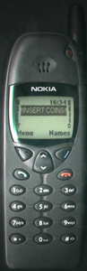
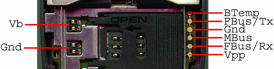
My humble 6110 and its pinout. Solidering wires directly onto the phone
does not hurt it if you were wondering. Since people have asked I have
put more connection pinouts at the bottom of this page, 8810,3310,3210,
8210, 8250
You have probably seen this schematic before, even though it said it is
for a 3210 it doesn't matter what model nokia you have. I have tested
it and found it works on a 3210, 6110, 5110 and 8210.
The above schematic is not much use till we run it though a PCB program, ignore the bad tracks in the image below, I have made a better one further down the page.
| Part no | Description | ||||||||||||||||||
| U1 | 78L05, 5 voltage regulator. Not the 7805, that will be too big for this project. | ||||||||||||||||||
| U3 | MAX232 IC, available in Australia from Jaycar or Dick Smith. Easy to get, every proper electronics shop in the world should carry this IC. | ||||||||||||||||||
| D1,D2 | Just your standard 1N4148 signal diodes. | ||||||||||||||||||
| C1 | Can be anything near 100uf. | ||||||||||||||||||
| C2 |
Just use anything between 1uf to 50uf, the voltage regulator won't care. |
||||||||||||||||||
| C3 to C6 | 10uf, can be 4.7uf or 6.8uf as long as these 4 capacitors, are the same value. | ||||||||||||||||||
| R1, R2 | 10 KOhm resistors | ||||||||||||||||||
| R3, R4 | 4.7 KOhm resistors | ||||||||||||||||||
| Q1, Q2 | BC547 transistors, BC548, BC549 will also work. | ||||||||||||||||||
| J1 |
Just holes in the PCB for attaching the wires. Connections are
as follows:
PS: for those wanting a cheap serial cable, don't cut the cord
off a old microsoft mouse like I did. Microsoft mice don't receive
data from the computer, and therefore only have four wires in the
cable. Useless for this project. Find an old Genius mouse they have
the neccessary number of wires. |
||||||||||||||||||
| J2 |
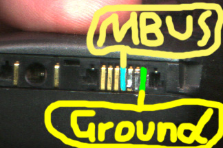
Mbus connection to phone, Pin 1 on J2 goes to the mbus connection on the phone. Pin2 on J1 goes to ground line on phone. |
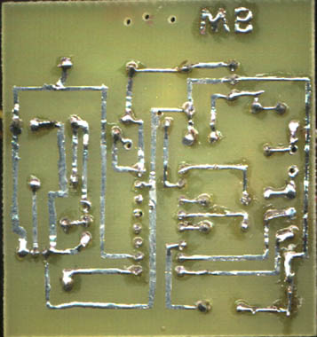
Now for the PCB tracks, you may notice that the tracks are slightly different to ones in the image above. I have just touched up some areas that the PCB software stuffed up. Also I have flipped the image ready for PCB printing.
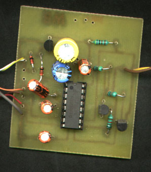
Which looks like this after solidering everything.
Ah! but one final thing. How do you attach the wires onto the phone?
Simple! just get some paperclips and tape.
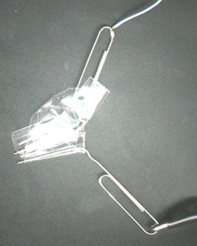 Tape them
together about 5mm apart leaving only a small amount of metal uncovered.
This is the cheapest way other than buying a hands free kit and pulling
it to bits.
Tape them
together about 5mm apart leaving only a small amount of metal uncovered.
This is the cheapest way other than buying a hands free kit and pulling
it to bits.
This interface works with any of these phones above.
Below: another 3210 connection pinout.
Mbarron Production
Email Me [email protected]